BrainSuite Diffusion Pipeline
BrainSuite can visualize diffusion data and perform brain connectivity analysis using tractography data and anatomical labels generated after cortical extraction. This requires co-registration of diffusion and T1-weighted anatomical images. The misalignment of diffusion and anatomical data can be caused by many factors, such as the movement of the subject in the MRI scanner and imperfections during the acquisition. This misalignment is also worsened by the geometric distortions inherent in Echo-Planar Imaging (EPI) sequences, which are the most widely used imaging sequences for diffusion MRI. EPI sequences are sensitive to inhomogeneities of the main magnetic field, which results in localized geometric distortions near interfaces of tissue, bone and air.
BrainSuite Diffusion Pipeline (BDP) corrects these geometric distortions in diffusion images, co-registers diffusion and anatomical images, and fits various diffusion models to the corrected diffusion data. Various different features of BDP is presented below with short description.
- DICOM-to-NIfTI Conversion: Most MRI scanners save images in the DICOM format. However, internal functions of the diffusion pipeline use the NIfTI-1 file format for storing and managing data. NIfTI files can also be visualized in BrainSuite and be used for further processing. The first step of using BDP is to convert DICOM (diffusion) images saved by scanner to NIfTI-1 format. The converted NIfTI files are saved to disk along with files that contain the parameters used to acquire diffusion data. Software packages, such as dcm2nii, can be used to convert DICOM files to NIfTI files, which can then be used for the pipeline (see usage page for more information).
- Registration-based distortion correction
- Fieldmap-based distortion correction
For registration-based distortion correction, BDP uses a constrained non-rigid registration based on mutual-information. It uses the bias-field corrected anatomical image generated by BrainSuite as a registration template and constrains the registration using spatial regularization and physics-based characteristics of distortion in EPI sequences. No additional data or fieldmap is required for registration-based distortion correction. For fieldmap-based distortion correction, a fieldmap should be acquired during the data acquisition which is used to correct for the geometric distortions. A rigid transformation is also estimated, using mutual-information-based rigid registration, to model any physical movement between the scanning sessions and differences in image orientation. Along with the distortion corrected diffusion images, the estimated rigid transformation is saved, which can be used to transform labels, volumes, surfaces and curves from anatomical (T1) space to diffusion space. Please see co-registration page for more details. (Bhushan et al., 2012)
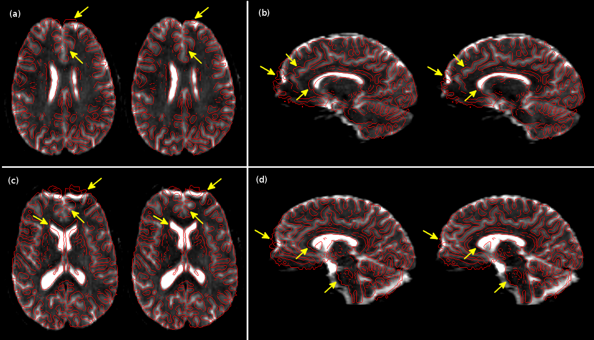
Results of registration-based distortion correction. In each sub-figure, we show (left) the distorted and (right) corrected b=0 image overlaid with the edge-map generated from T1-weighted data (in red). The arrows indicate a few of the locations of significant correction (Bhushan et al., 2012).
.eig and .odf file respectively and can be visualized in BrainSuite as shown below. (Haldar and Leahy, 2013).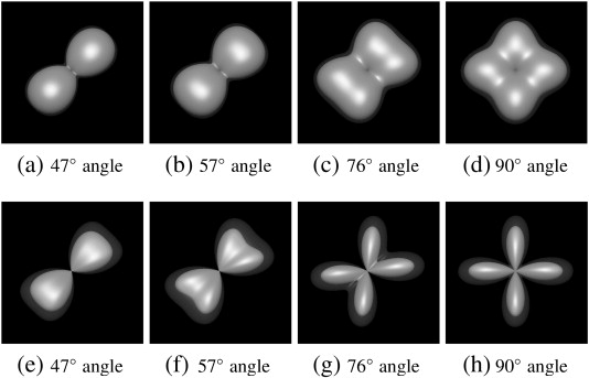
Qualitative comparison between the FRT and the FRACT at a b-value of 2000 s/mm2, in a two-tensor simulation with SNR = 20, N = 256 directions, ξ = 0.34ρ, and L = 8. Each image shows the mean ODF (solid) and the mean ODF plus two standard deviations (transparent). Results are shown for (a)–(d) the FRT and (e)–(h) the FRACT, for crossing angles of (a and e) 47°, (b and f) 57°, (c and g) 76°, and (c and g) 90°. (Haldar and Leahy, 2013)
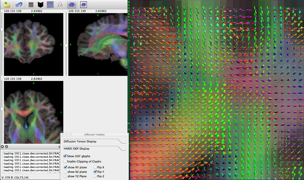
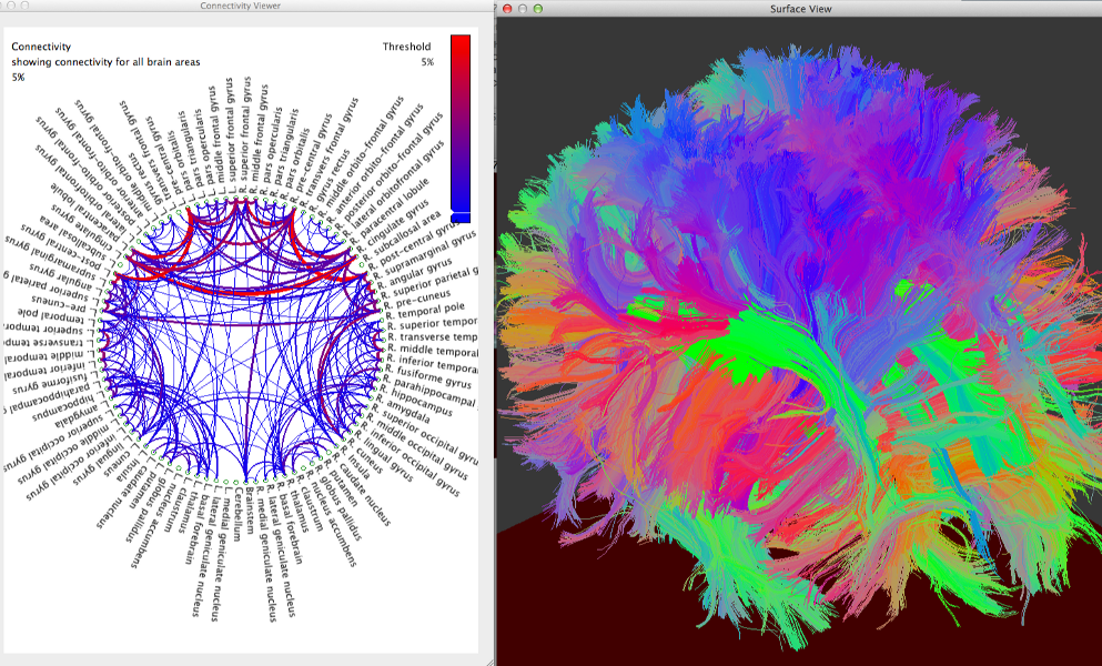
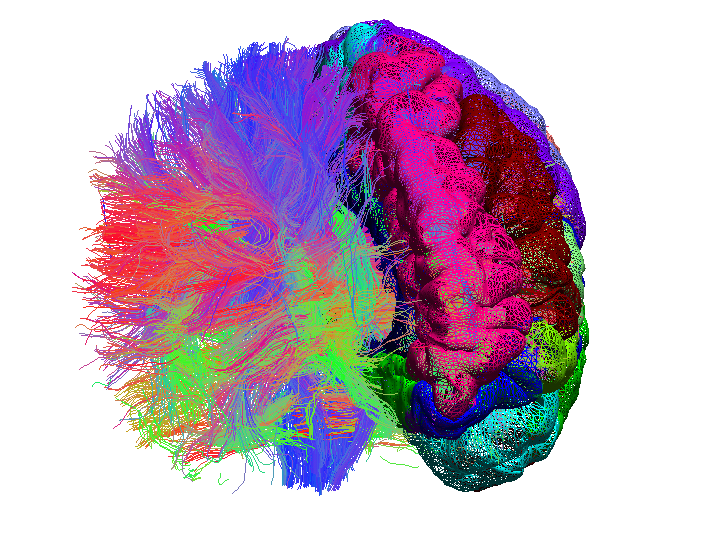
BrainSuite interface showing ODFs in surface view.